I realize this story is going to be pretty elementary for anyone with an electrical engineering background, so I apologize for that. For everyone else, I hope that you can find my experience useful!
Phase 1
In December, I pulled out a bunch of audio gear with the intention of writing some music. It had been a a bit too long; 2016 was filled with tons of small side projects so I had limited free time. I sadly discovered all four of my MIDI controllers were broken in some way. I spent a few weeks searching for a replacement before I realized that anything fitting all of my requirements was going to be expensive. You can easily spend $600 on a MIDI controller that isn't a piece of garbage, at which point you could say "why am I not buying a synth?" But that quickly climbs to the thousands of dollars for anything I want. So there was really only one thing left to do: build my own synth!
I had enough parts to start building something, though I lacked the technical foundation in electrical engineering to know how to supplement those parts. Fortunately, Google is amazing!
Maybe I spent about a week reading articles online on electrical engineering basics. There's a ton of information there, so I don't have to elaborate on how to find it. Though I will say starting with Wikipedia before hunting for specifics with Google was a successful combination for me.
The obvious way I thought I would handle this project would be to split it into separate phases. Essentially, I would start by building a MIDI controller, and then later I could add DSP in the firmware to turn it into a synth.
My planned phases: 1. Get a microcontroller reading input from a key-bed and have it output MIDI messages 1. Add potentiometers to the microcontroller to adjust various parameters 1. Build the chassis for all my parts 1. Write the DSP code to convert my MIDI controller to a synth
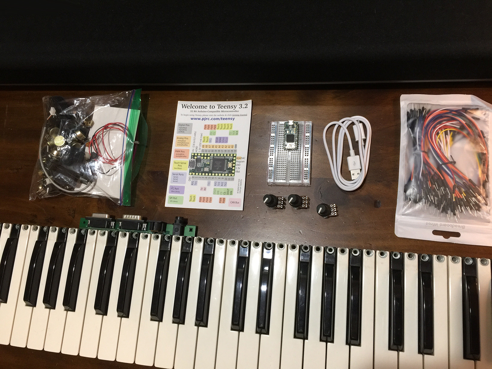
Fortunately, one of my broken controllers had a decent 49-key key-bed that I was able to rip out and re-use for this project. Between the rest of the controllers, I was able to save 18 pots. This all seemed pretty promising. After looking around a bit, I decided to go with a Teensy 3.2 for the microcontroller. Teensy is a great Arduino-compatible AVR microcontroller. It's fairly inexpensive (I spent $24 for the Teensy, plus headers already soldered on, and a breadboard.)
Now, this particular key-bed supports velocity sensitivity, and it achieves this by placing two switches on each key at different heights. When you begin to depress a key, the first switch closes, and when you fully depress a key both switches are closed. To discover the velocity, you just need to measure the time between the two switches closing and plot it on a velocity curve. More on that later, but for now that means I needed to have 98 inputs going into the Teensy.
The bad news is, Teensy doesn't have 98 inputs. The good news is, since they are all digital inputs (they have a binary state, either on or off) it would be incredibly simple to multiplex them.
The most common way of multiplexing on a keyboard is to use a keyboard scan matrix. There is definitely some decent information out there on matrices, but this article was particularly helpful to me. The gist of it is, you can use a matrix of wires where you send power to the columns individually and read all of rows for each active column. Then, each key becomes an intersection on the matrix. It's pretty great, because with (for example) 8 wires configured in a 4x4 matrix, you can read 16 inputs. My key-bed already had two 8x8 matrices outputting from the perfboard. It was just a matter of figuring out where all these wires mapped to, and how I should read them.
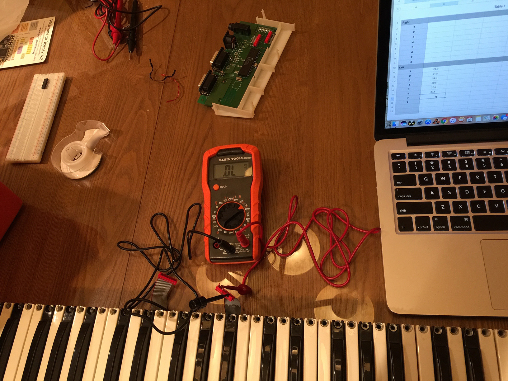
Of course, nothing is ever easy, and my father's old Radio Shack multimeter that I've been using for the past couple of decades finally breathed its last breath. I tried some quick repairs, but it became obvious that I was going to need a multimeter to repair my multimeter. Oh, well... maybe that's a project for another time?
With a new multimeter, I ran a continuity test on the wires. I pressed a key on the keyboard and tested every combination of wires until I found the combination that gave me voltage. This was an incredibly long and boring process, but unfortunately there wasn't much I could do to avoid it. It did, however, allow me to map a spreadsheet of the wires and all of their values. The first matrix didn't actually start with the first wires, so that was going to be valuable information later.
After the matrices were mapped out, I could now work on reading them. The concept is pretty simple, I just needed to send Vcc from my Teensy to each column in the matrices in sequence, and read all 16 rows with each loop.
Now, if I just read all of the inputs from my matrices directly into the Teensy, it would certainly be condensed from the original 98 inputs, but I would still need 32 inputs to read everything. This wouldn't leave me room for my pots, or anything else later on, so I needed to multiplex this down a bit further.
Shift registers turned out to be a great simple solution to this problem. There are various kinds, but the most common work with 8 bits. The Serial-In Parallel-Out (SIPO) register allows you to use 3 output pins on your microcontroller to control 8 outputs. The Parallel-In Serial-Out (PISO) register allows you to read 8 inputs serially using only 3 pins on your microcontroller. The caveat is that you are now converting between serial and parallel communication channels, but this makes things way more manageable and still processes well within the 20ms MIDI timing spec so it was a win.
There are actually quite a few different types of shift registers which allow you to do neat things like locking (Google it), but for the scope of this project that was entirely unnecessary. I decided to use the 74HC164 and 74HC165 since they are dead simple for what I wanted to do.
It's worth noting here, read the data-sheets for any components you want to buy thoroughly before you purchase anything. I did quite a bit of testing ahead of time, and it saved me tremendous headaches and time down the road.
All of this was still planning, of course, and before I actually purchased anything I wanted to make some digital prototypes. I found a piece of software called iCircuit, which I totally fell in love with. Not only can I architect my circuit diagrams with it but it allows for a simulation mode which assists me in catching things like matrix singularities and all sorts of nastiness I would rather not deal with in real life. It's incredibly invaluable, and well worth the money. The only problem I had was that iCircuit doesn't have support for the 74HC165. It does have the 74HC166, which was close enough for me to prototype with.
So, using iCircuit, I built a few test circuits, tested how they might work, made adjustments, and repeated until I had something I liked.
Finally, I purchased parts from Amazon and later from Jameco Electronics. @JamecoOnline was actually pretty great, and now that I know they are an option I think I will be making all of my parts purchases from there.
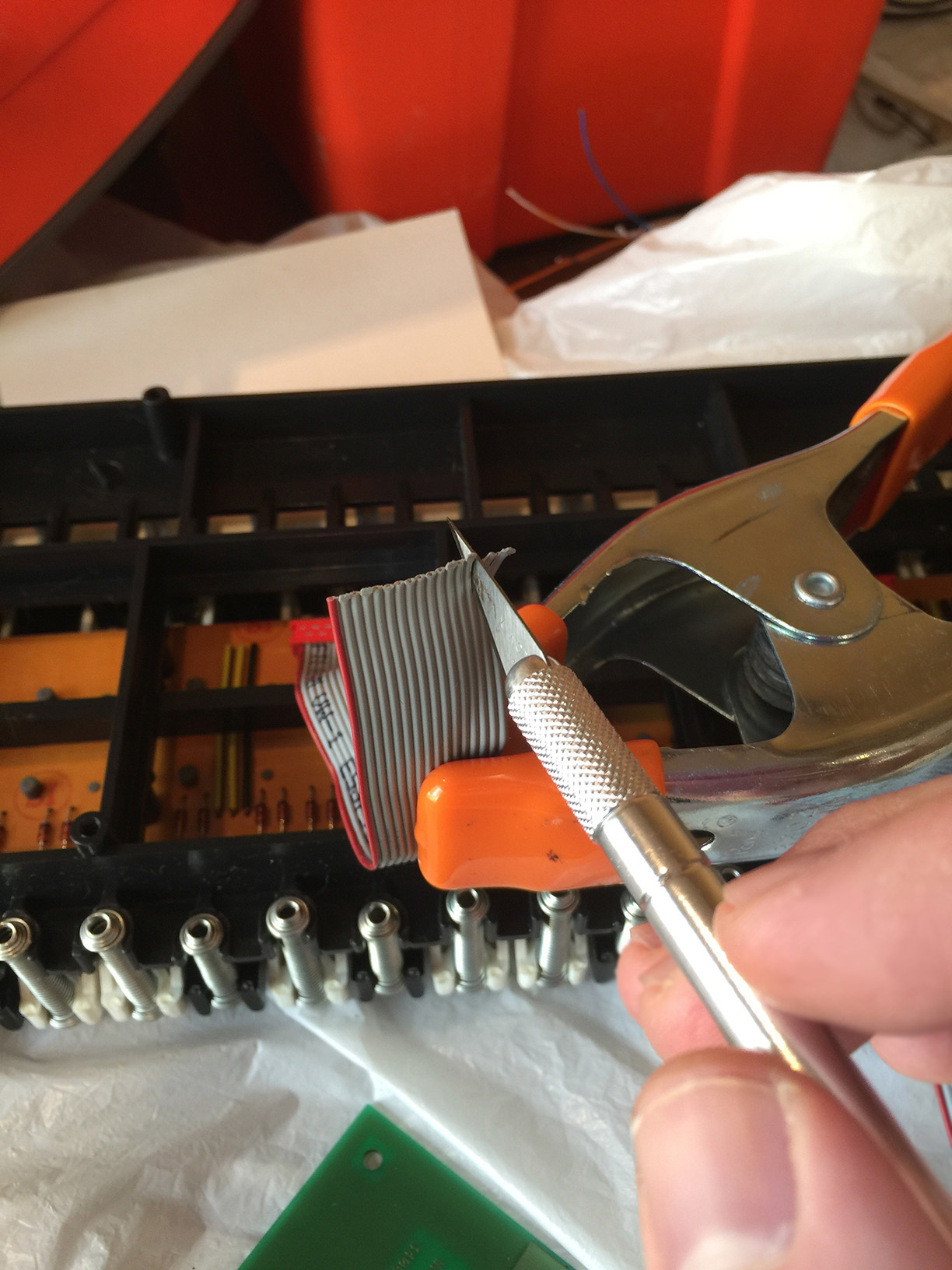
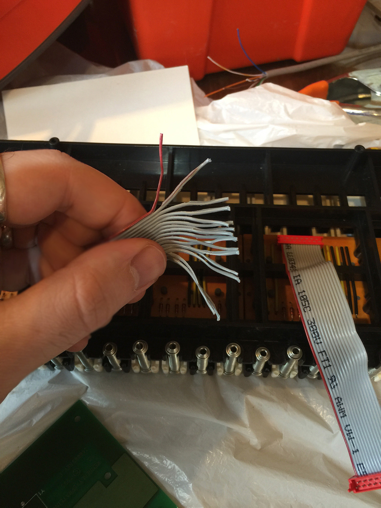
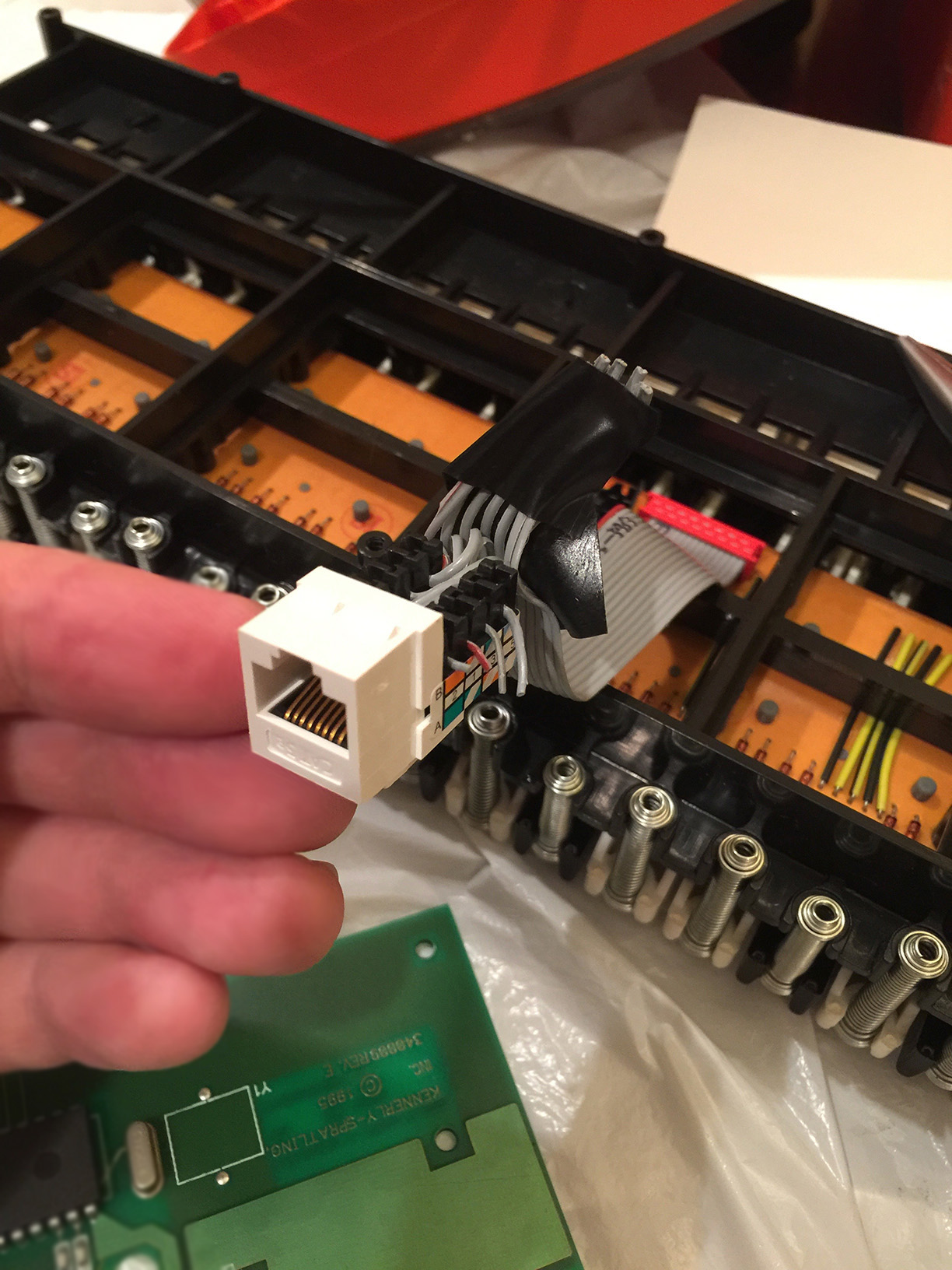
I did overlook one thing, unfortunately. The ribbon cables that originally came with this key-bed were fairly short, and uses micro-match connectors. Ideally, I should have ordered new ribbon cable, a micro-match crimper, and new terminating heads. The crimper alone can be close to $1000, and I really didn't feel like waiting a few more days for parts, so I decided to work with what I had on-hand. I ended up cutting one end of the micro-match cables off, and splicing them into RJ-45 terminating jacks. With those, I could then making custom CAT5 cables that were terminated on one end, but stripped and exposed on the other. It was far from ideal, but it gave me something I could work with that would plug in fairly nicely to my breadboard. CAT5 can definitely handle the Vcc of the Teensy well (Teensy is only 5V and under 1amp which is within the CAT5 spec.) Though it didn't look pretty, it got the job done.
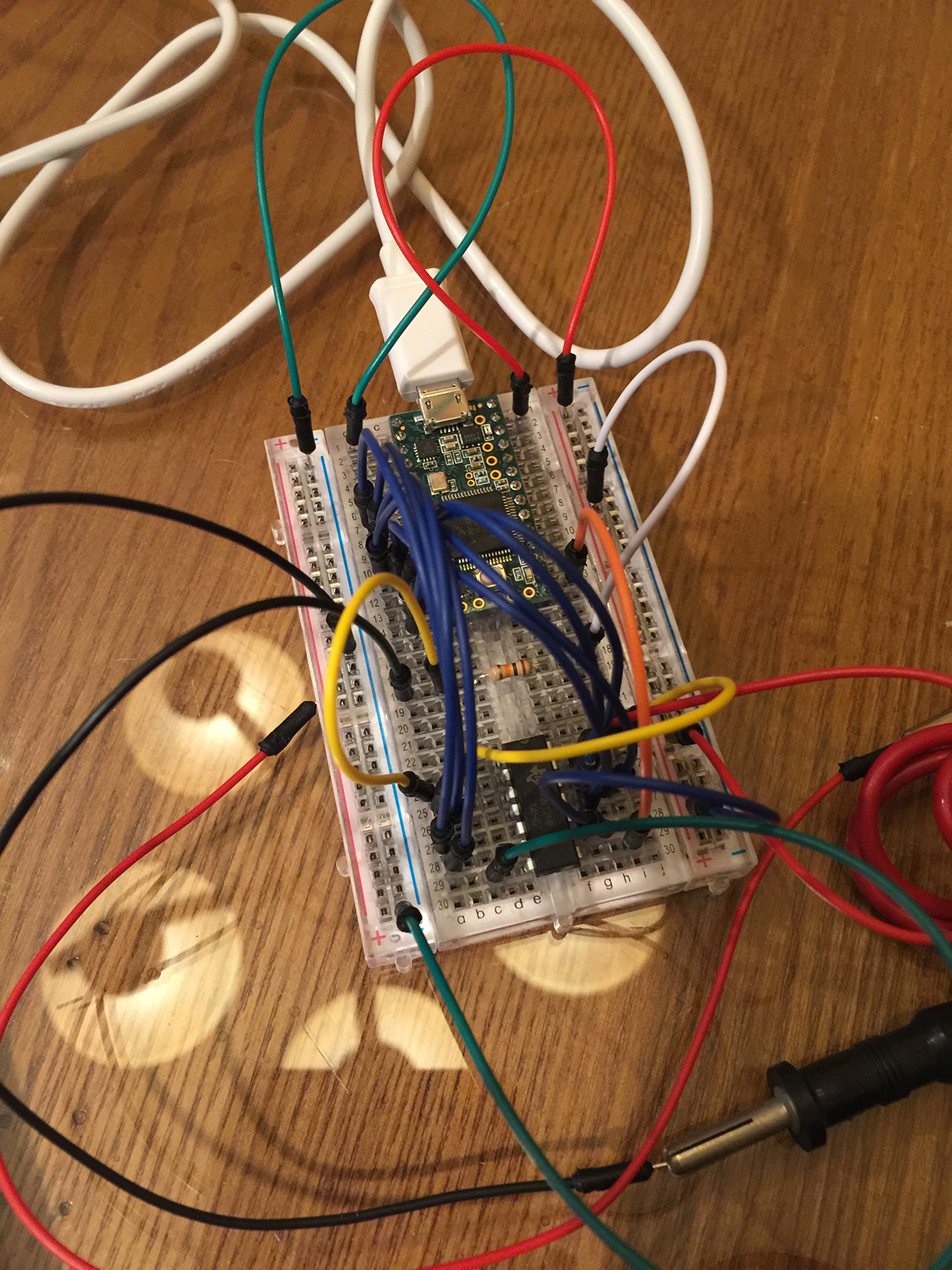
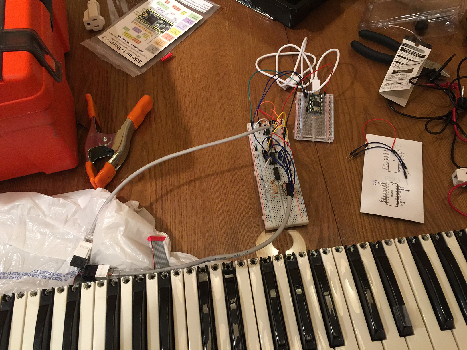
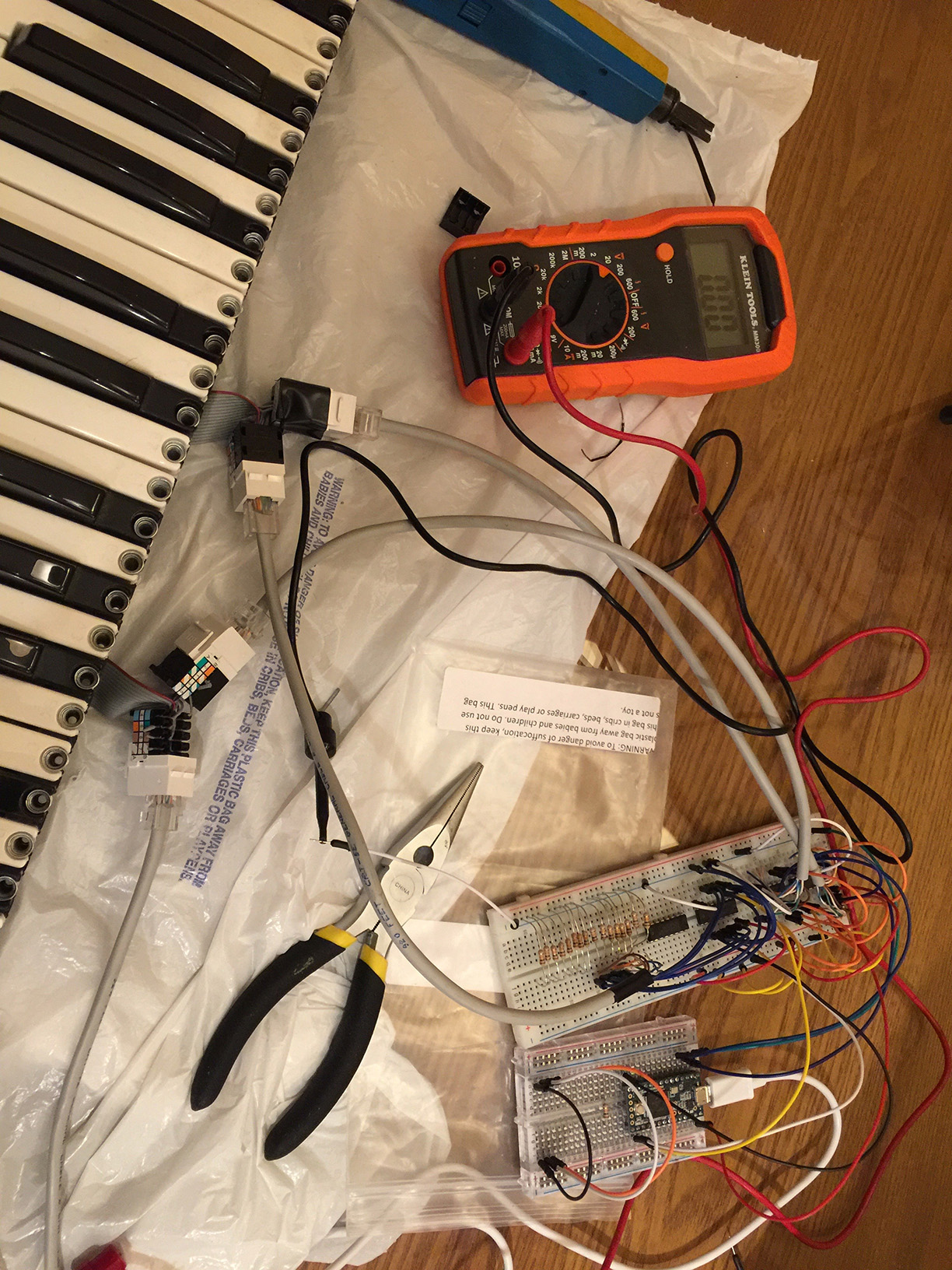
Plugging in all of my components and wiring them up was pretty easy. But it did require a bit of troubleshooting. When you have a mess of wires running all over your breadboard, it's easy to err and plug in all of your wires to your shift register shifted 1 pin off position (ironic, I know.) I was troubleshooting some incorrect values by putting the multimeter to every pin at every point in the chain before I discovered what I had done. If at all possible, I would recommend using cables just long enough to fit your specific project (which probably means make them to length when you need them.)
Once the hardware was in place, and I could confirm that all my continuity tests were working, I was able to write the first version of my firmware. Like Arduino, the Teensy is just a dialect of C so it was incredibly straight forward. There was plenty to troubleshoot. I could have used SPI to control the shift registers, for example, but I wouldn't really learn much about the shift registers if I did that. I decided to pulse and poll the chips manually, which was a lot of fun. I started with a function to read my PISOs (shiftIn165()) which worked as expected, and then expanded from there. That does introduce the concern of endianness, but it is a trivial problem to solve. With ~140 lines of code, I had a a working first draft of my firmware. The velocity curve was simple (linear) but it works for this part of the project.
Velocity
Personally, I think velocity is quite an interesting subject. Grabbing the timing between two switches on a single key is really easy. However, plotting that time measurement on a velocity curve gets to be a lot more complex. One might assume that there's a 1:1 ratio with time and velocity. The faster you press the key, the faster the velocity. This can be represented with the formula v = 127 - (t / (m/127)) where t = time calculated and m = max time before a value is equal to 127 (The max value of a MIDI message). But it's not exactly satisfying to play. It's not awful, but it's not great. There's been quite a bit of time and research dedicated to this very topic; you would be amazed at seeing the thought that goes into manipulating a satisfying velocity curve. It's for this reason that so many professional synths have a varying range of (and sometimes adjustable params for) velocity.
This is something I will put some more effort into in phase 4 of this project. I am tempted to use some sort of Bézier curve to solve this problem, but I will need to read more about it first! In the meantime, I am using a slight variation of the above formula for prototyping.
At last!
My old key-bed is breathing new life as a MIDI controller! It has been a lot of fun so far, and I can't wait to start phase 2.